
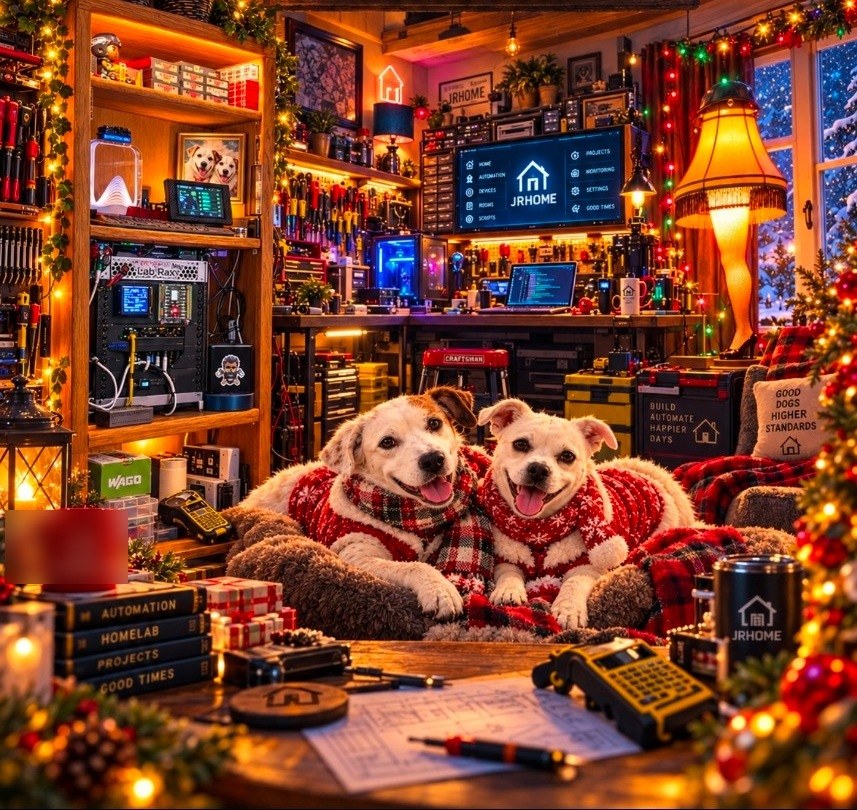
What started as “I should do something better with the Christmas lights this year” turned into a dedicated branch of my home platform: a fused, fan-cooled, Ethernet-connected outdoor control enclosure, 500 addressable pixels, 40 lighting looks, a Holiday page on the touchscreen and a schedule in Home Assistant.
I’ll tell it in the order it happened, including the measurement that changed my plan. One caveat up front: the node is built, powered and working on the bench, and it’s tied into the platform. The final outdoor install and its last measurements aren’t done yet, and I’ll say so where it matters.
At a glance
| Node | JRHome Christmas Field Node 1 |
| Controller | GLEDOPTO GL-C-618WL Elite running WLED 0.15.4 |
| Power | Mean Well LRS-350-24 (24 V DC, 350 W) |
| Lights | ALITOVE 24 V WS2811 pixels, about 4 inches apart, five strings of 100 |
| Protection and wiring | Blue Sea 12-circuit fuse block, DIN-rail terminals |
| Connection | Ethernet through an IP68 bulkhead, flanged AC inlet |
| Integration | Home Assistant, a Holiday page on the 10.1-inch touchscreen, 40 looks |
| Status | Bench-operational and integrated. Outdoor install and final measurements pending. |
Why a node, not just a controller
I didn’t want one computer driving every light. The platform already works in layers: Home Assistant handles scheduling and coordination, the touchscreens give the household an interface, and independent field nodes do the physical work.
So the Christmas node runs its own lighting through WLED. If a touchscreen reboots, or Home Assistant restarts, the lights keep running what they were running. That also makes it expandable: the next lighting zone can be another node without redesigning the first.
I also wanted equipment I could maintain and reuse across seasons, not a disposable consumer box: serviceable terminations, fused branches, a fan, a bulkhead connector for the network cable, and a power inlet I can unplug when the season ends.
Choosing the hardware
- Power: a Mean Well LRS-350-24, a 24 V, 350 W supply.
- Controller: a GLEDOPTO WLED controller with Ethernet and multiple data outputs. WLED already has the effects, presets and playlists I wanted, so I could spend my time on integration instead of writing lighting firmware.
- Pixels: 24 V WS2811 bullet pixels, which suit long outdoor runs better than 5 V. Five strings of 100, about 4 inches between pixels.
- Distribution: a fused block for the branches, DIN-rail terminals for connections, a 24 V fan, and a thermostat planned to control it.
- Enclosure: a vented steel outdoor cabinet, an IP68 Ethernet bulkhead, a flanged AC inlet, and a small white COB light strip inside so I can see what I’m doing during service.
The design keeps pixel power and pixel data separate. The controller sends data, while the heavy current runs through fused, properly sized wiring instead of the controller’s small terminals.
The measurements that changed the plan
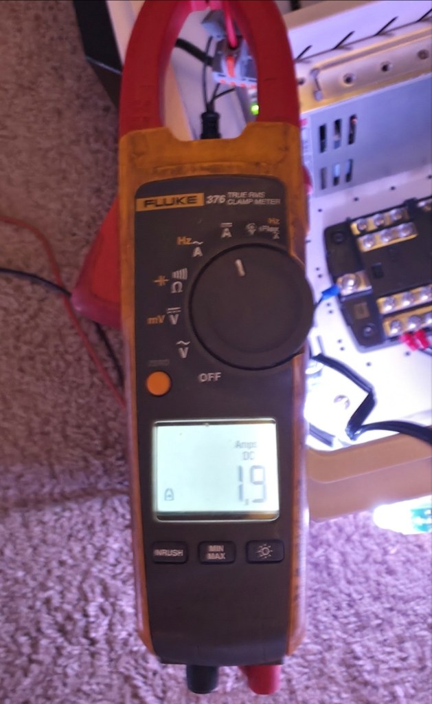
This is my favorite part, because the data overruled my assumptions. I used a Fluke clamp meter and direct voltage readings on the bench.
- The supply read 24.1 V with no load.
- One 100-pixel string at full white drew about 0.9 to 1.0 A at 24 V, roughly 24 W, or about 10 mA per pixel.
- Two strings drew about 1.9 A, which agreed with the first number.
Then I looked at the voltage at the far end of the run:
| Test | Voltage at far end |
|---|---|
| Two strings, low-brightness white | 23.6 V |
| Two strings, full white | 17.7 V |
| Three strings, full white | about 10 V |
| Five strings, full white | about 7.5 V |
Two strings at full white lost about 6.4 volts, more than a quarter of the supply. With all five in series, the total current was only about 2.9 A, not because the lights needed less, but because the far end was starved. Chaining strings end to end and hoping would not have worked.
The answer is power injection: feeding 24 V and the return conductor to the start of each 100-pixel segment, with the data still running in series. I’ve chosen to do the final injection measurements outdoors, where the real wire lengths and layout will decide the numbers. So the bench investigation is finished, but the final injected end-of-string readings are not recorded yet, and I won’t quote any until they are.
Two smaller discoveries from the bench:
- The colors were wrong. The factory WLED setting assumed one color order, and my pixels needed another. Switching the order to RGB fixed it.
- WLED’s default power estimate was far too cautious for these pixels and was quietly dimming everything. After measuring, I set it to 10 mA per pixel and a 5,000 mA limit for the bench. Those are bench settings, not a substitute for the final branch protection.
Building the panel
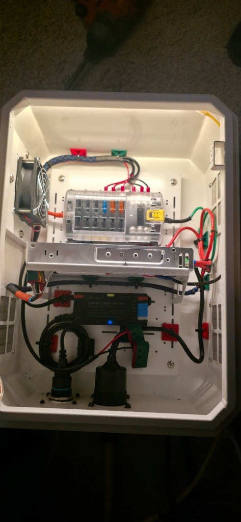
Everything mounts on a backplate, laid out the way a small electrical panel would be: power supply, fuse block, controller, terminals, with grouped wiring I can trace. The connections come in through the bottom, so I can unplug the power and network cable at the end of the season and carry the enclosure away. A short internal patch cable runs from the Ethernet bulkhead to the controller.
Because the cabinet will be unplugged for part of the year, I built the platform to handle that honestly. When the node isn’t there, Home Assistant sees it as unavailable, and the panel reports that, rather than showing the lights as simply switched off.
Tying it into the platform
Home Assistant talks to the node through its standard WLED integration: on and off, brightness, presets and playlists, whether it’s available, and a switch that enables or disables the Christmas schedule. A Home Assistant package runs that schedule, from sunset to midnight and again from 4 to 6 AM, with catch-up after a restart that leaves whatever look was running alone.
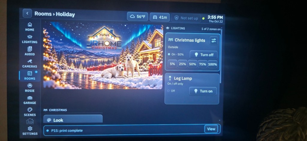
The 10.1-inch panel got a Holiday page. It’s not a separate holiday app, just a seasonal extension of the normal interface: the same navigation and rules, with the Christmas artwork, the lights’ on/off and brightness, the looks, and the schedule controls. It also lets that one page stay on screen without the idle screen taking over. A seasonal rule makes it appear under Exterior from November 1 to January 10; for now it stays reachable under Rooms, and I’ve confirmed it’s correctly hidden from Exterior today. The first real test of that is November 1.
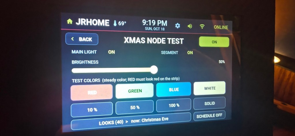
On the bench, a 5-inch Satellite doubles as the test screen: on and off, brightness, red, green, blue and white test colors (red has to look red on the strip, or the color order is wrong), and the looks list. It isn’t part of the node’s operating path. It’s another example of the platform letting an existing screen help with a new piece of hardware.
The fun part: the looks
The node holds 40 looks, 34 individual presets and 6 playlists. I treated them as design work, not a pile of effects: traditional warm white and classic multicolor, candlelight, candy cane, winter blues, and gentle twinkling, then more ambitious pieces.
- Game-day colors: a calmer set and an energetic set in a favorite team’s navy, bright green, gray and white.
- Spectrum Odyssey: flowing color with comets, bursts and aurora-like effects.
- Griswold’s Greatest Hits: an almost five-minute playlist that moves through traditional scenes, builds to something wild and settles back down.
- Quieter playlists: a few more-restrained ones, built around candlelight, warm twinkles, fairy lights, starfields, icy twinkles and Northern Lights, each a few minutes long.
- A playlist built around my wife’s favorite colors: soft pinks, rose gold, lavender, champagne and pearl.
Where it stands
Done and working: the power supply, controller, Ethernet connection and WLED configuration; single-string and two-string tests with measured current; the measured voltage drop on longer runs; the assembled enclosure powered on the bench; the Home Assistant integration; the Holiday page; the schedule; and the 40 looks.
Still to do: final enclosure inspection, fuse and wiring coordination, fan-thermostat verification, outdoor mounting, the seasonal power and network connections, the power-injection installation with full-white voltage readings at the end of each string, field visual acceptance, and a written seasonal teardown and storage procedure. I haven’t installed the exact number of pixels that will go outside, either. The five-string bench test was a measurement, not the final layout.
What I’d tell you if you’re building one
- Measure before you design the power. My assumption would have been wrong by a factor of two at the far end of a long run.
- Check the color order first. Red must look red.
- Don’t trust a controller’s default power estimate on a different pixel voltage.
- Keep the data path and the power path separate in your head, and in your wiring.
- Build it so you can unplug it. Your future self will be standing in the cold.


Leave a Reply